IMAbypass Kit Install Instruction
Tools needed:
One 10mm socket with rackets or one 10mm wrench
Tool to disconnect the negative side of the 12v battery, usually 10mm wrench or 10mm socket with rachet.
Scissors
Multimeter
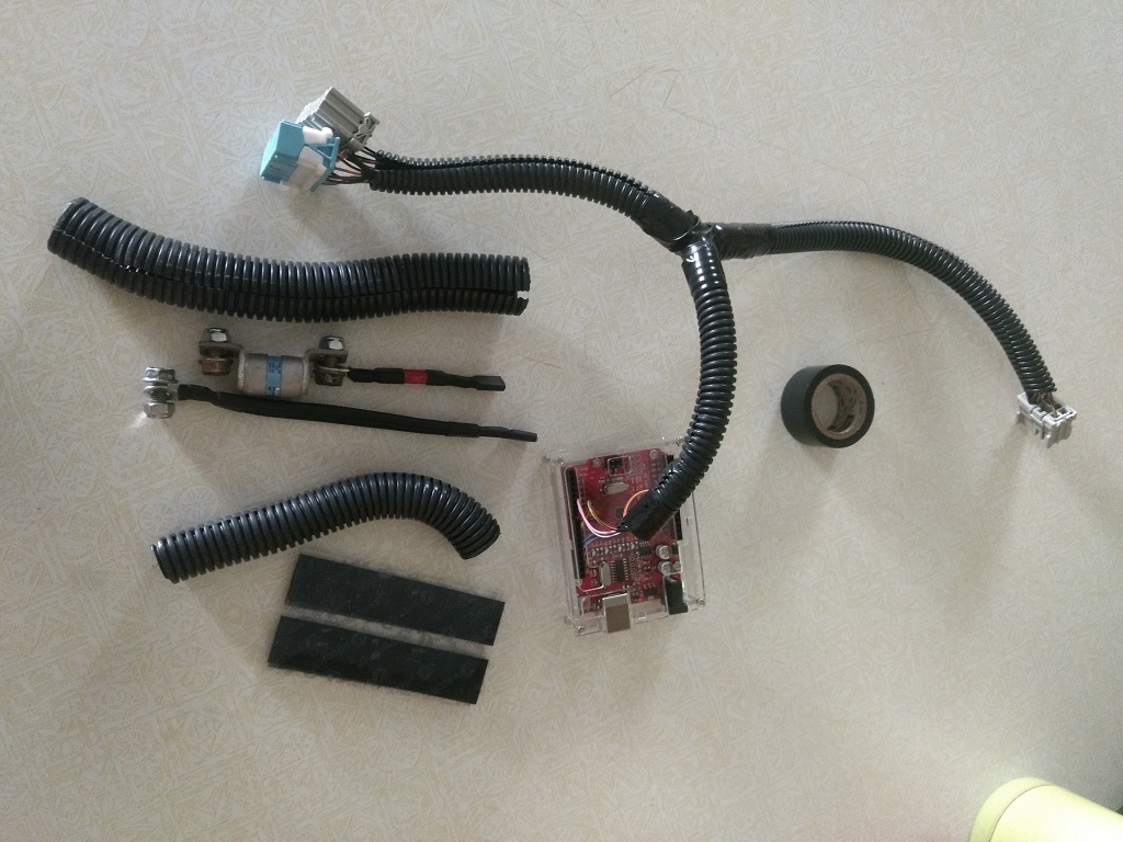
The IMA bypass kit comes with:
The Arduino in plastic case with the 3 connectors
Black wire with a ring end and female spade end
20amp fuse with red wires with a ring end and female spade end
Wire loom
Electrical tape
Three set of nuts and bolts
Velcro
WARNING:
You’re installing this kit at your own risk. There is no imply or express warranty with this kit. If the kit is not correctly install, serious injuires/damages WILL OCCUR.
If you do not agree, stop now!
1. Getting ready to install
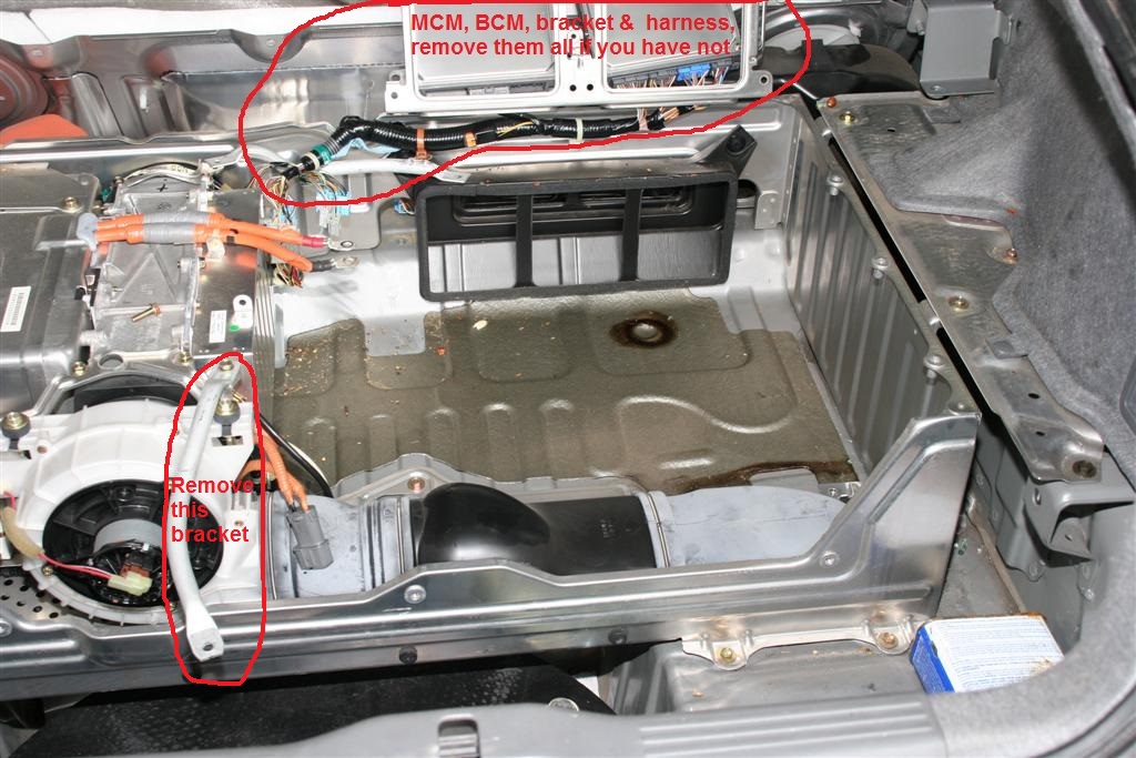
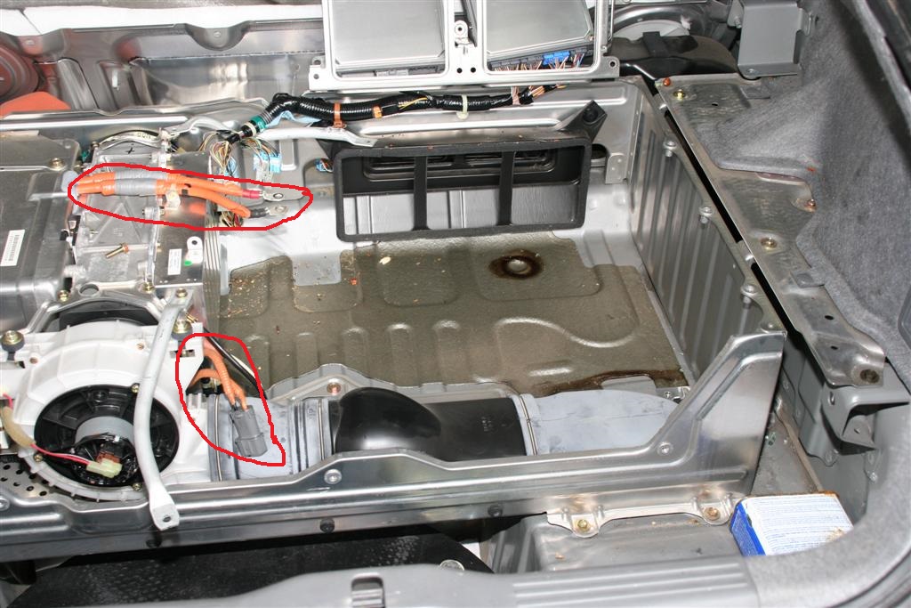
Use the BubbleBee guide to remove the IMA battery.
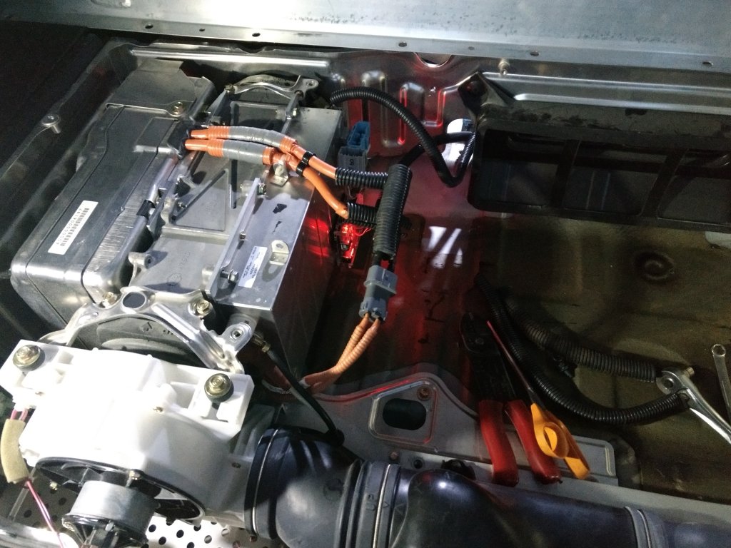
Your IMA bay should look like this after you remove the battery. (BCM, MCM, brackets and harness is still in the picture, remove them all if you have not.
2. Installing IMA bypass kit
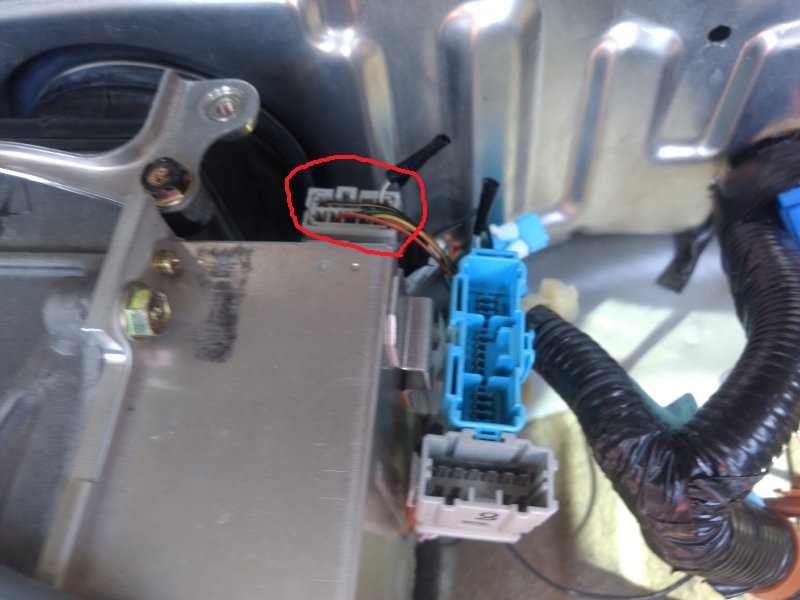
Install the Arduino by plugging the three connectors as below pictures.
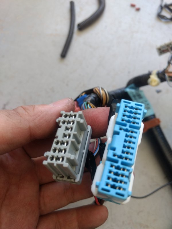
Goes into
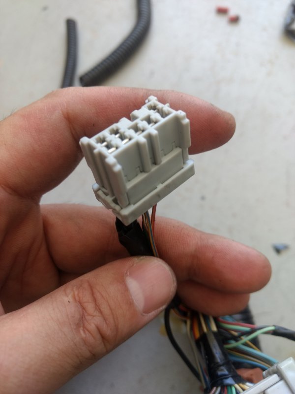
Goes into
Secure the Arduino with the velcro provided with on a horizonal surface.
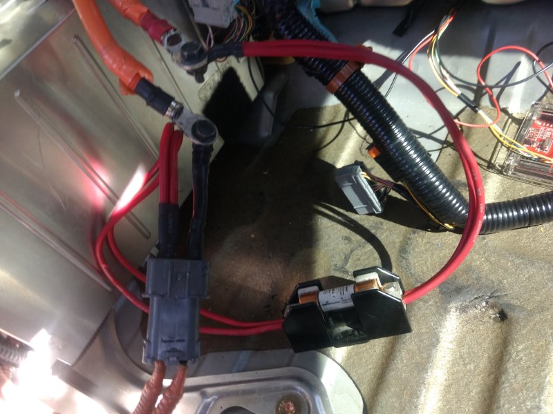
Now, we'll be connecting the orange wires.
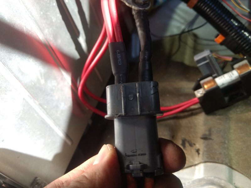
Bolt the orange wires with red ends to the fuse first then slide the spade end into the grey connector near the white fan.
Bolt the orange wires with black end to the black wire and then slide the spade end into grey connector near the white fan.
Warning, make sure the female spade connectors are securely connected to the male end of the spade connectors. If not, 12v battery will not charge.
Photo is from a prototype kit with extra long wires.Your kit have much shorter wires.
Tighten all bolts and nuts.
I marked my connector with red paint as a reminder of which wire goes where.
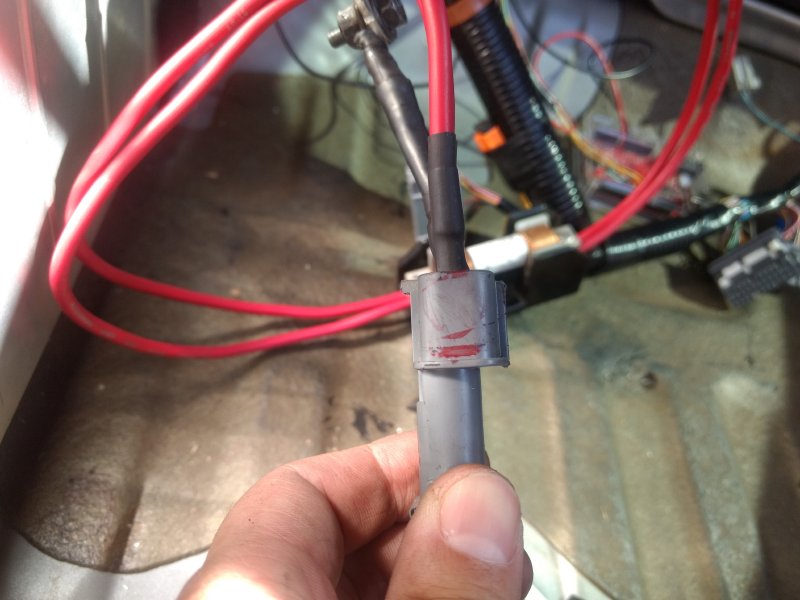
Warning, make sure the female spade connectors are securely connected to the male end of the spade connectors. If not, 12v battery will not charge.
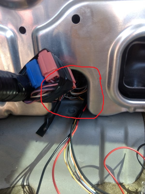
Secure the fuse/wires/connectors with generous amount of electrical tape and wire loop.
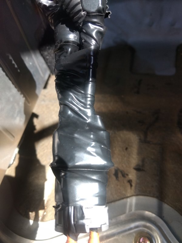
Example of an almost finish install picture. (Needs more electrical tape so secure the spade connectors)
3. Testing and close lid
Reconnect the 12v battery, then start the car to make sure IMA/CEL lights are not on and 12v battery is being charge using a multimeter.
If it pass the test, turn off the car, and follow the BubbleBee guide to close the lid.
Expected IMAless behaviors:
IMA is disabled, including instant start of the ICE (interanl combustion engine)
Autostop is disabled
Regeneration is disabled
CEL is off
IMA is off
Lean burn is enabled
6500 rpm redline
Start delay, you have to hold the key for 3-4 seconds for conventional starter to start the ICE.
12v battery charging happens above 1200rpm(depends on electrical load) to 4000rpm. If the engine idles long enough and (30mins+ on a health battery) running a/c, your 12v battery will run down.
Brake and Battery light will come on above 4000rpm
Above 4000rpm, the DC to DC converter will stop 12v battery charging, battery and brake lights will turn on and stay on between 30 seconds to about 3 minutes. Afterward the DC to DC reset itself, the battery and brake lights will turn off and 12v charging will resume.
Reference:
Modify the starter relay so the car will crank on conventional starter first time you crank it. Note: This modification will bypass the neutral safety switch
Original IMAbypass thread